hubbatech
Projects,
articles and links to information that may interest Radio Amateurs and
Electronics enthusiasts
.com.au
|
hubbatech
|
Projects,
articles and links to information that may interest Radio Amateurs and
Electronics enthusiasts
|
|
.com.au |
|---|
HOW TO BUILD THE PAGER FILTER
If you took the time to read the notes leading up to this part then you may want to build one of these filters for yourself. It is very easy and with all the required parts should take no more than an hour assuming that the tuning is done afterwards.
The tube is simply a 65mm length of 50mm diameter copper plumbing pipe. A scrap metal yard is a good source of short lengths. The helix is wound using 3mm thick copper wire. I was lucky enough to unwind a spare high current transformer and obtained enough wire to do all my experiments with. Wind 6 to 7 turns on a 25mm former and allow it to slightly expand when it is removed. Stretch the helix to about 50mm long and bend the last 30mm of what will be the bottom (cold or earthy) end of the helix at right angles so that it can be passed through a hole to be drilled in the side of the pipe and soldered in place. This hole and the BNC mounting holes are all 15mm from the bottom of the pipe. The hole for soldering the cold end of the helix is about 20mm from the BNC hole. Try to keep the windings of the helix uniformly spread but this can be finely adjusted when the helix is mounted inside the tube.
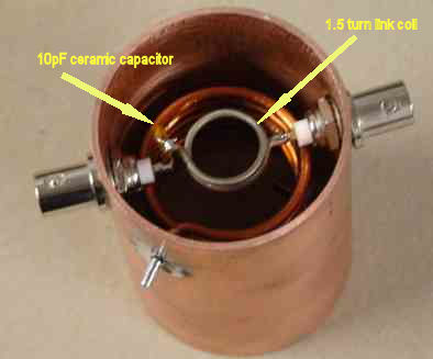
A 1.5 turn coil needs to be wound using slightly smaller diameter wire onto a 15mm diameter former. Both ends of the coil are bent at a right angle leaving about 20mm of straight wire. This coil will be mounted centrally between the centre pins of the BNC connectors however one end will be cut short and a ceramic capacitor will be soldered in series. The value for this capacitor I found to be 10pF. You could try other values if you want to put the extra effort in to see if better results can be obtained in both the notch and SWR.
The holes for the BNC connectors are drilled 15mm from the bottom of the tube and are 180 degrees opposite. I used panel mount connectors with a thread and nut on the body.
The 1.5 turn coupling coil and 10pF capacitor in series with it are mounted just inside the bottom loop of the helix coil instead of outside of the helix.
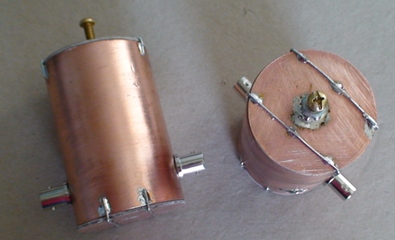
The end covers are really for physical protection of the internals of the filter and a convenient method of providing tuning. They were made from double sided PCB using a circular hole saw in a drill. That left a hole in the centre which I used at one end to insert the bolt for tuning and left the other end open. The tuning bolt is brass and 50mm long with two nuts; one of which is soldered to the top of the end cover and the other is used as a locking nut when tuning is completed. Solder a copper or brass disc of about 12mm diameter to the inside end of the bolt. This will give variable capacitance for tuning the helix to the notch frequency.
To obtain the best Q, it is best to cut the helix to just slightly higher than resonance without the bolt tuner. The helix can be expanded and compressed carefully trying to keep uniformity in the windings and the turns spacing. You should end up with about 5.25 turns on the helix. After the end cover is installed, the notch frequency can be tuned down with the bolt adjuster. This method is quite accurate. If you are suffering from interference from multiple pager transmitters on different frequencies, you may need to tune the helix somewhere between the frequencies aiming to be closer to the frequency of the stronger transmitter frequency than the others.